End-effectors & TCP
A bare robot moves its flange (the J6 mounting face). Once you bolt on a gripper, vacuum cup, pen, or spindle, you care about where the tool tip goes, not the flange. That tip is the TCP, the Tool Center Point. Egret lets you both see the tool on J6 and aim moves at its TCP.
The quick way: tool presets
Two drop-in components carry their own geometry and TCP so you don't have to model anything:
- Gripper Tool, a two-finger parallel-jaw gripper.
Openingsets the jaw gap,Finger Lengthsets how far the tip sits from the flange. The TCP lands on the jaw line. - Vacuum Tool, a suction cup on a stem.
Cup DiameterandStem Lengthsize it; the TCP lands on the cup face.
Each one takes your Targets and gives back three things:
- Targets, the same list, now stamped with the tool's TCP offset (so Stage and the generated code work at the tip).
- Tool Meshes, the tool drawn in the flange frame.
- TCP Plane, the working point, for reference.
- Tool, the whole tool bundled (geometry + TCP + payload), to drop into the Robot picker's Tool input (see below).
The easy way: attach the tool to the Robot
Drag the tool component's Tool output into the Robot picker's Tool input. The tool then travels with the robot across the whole canvas, every component that resolves the Robot sees it, with no extra wiring:
- Stage draws it on J6 and puts the TCP at the tool tip
- Collision includes the tool geometry, catches the tool hitting the arm or a fixture
- Code emits
set_tcp_offset+set_tcp_load(payload) - Cartesian moves aim at the real tip
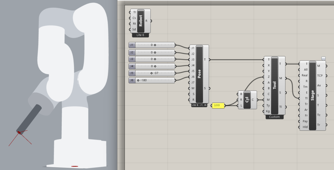
Drop one Robot picker with a tool and the entire graph follows it, even unwired components find it. Grab the tool-on-robot example (.ghx) to see it end to end. (Tool components live under Egret ▸ Tools.)
Or wire the mesh into Stage directly
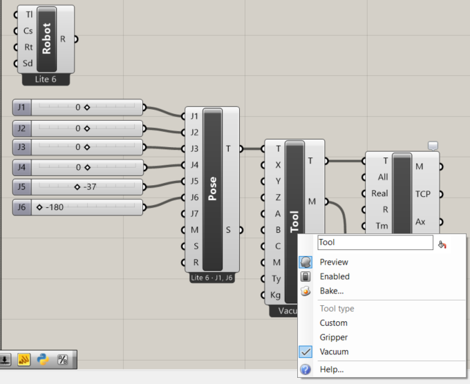
Stage also has a Tool input, wire the tool's Tool Meshes
output into it to draw the tool on J6 without attaching it to the Robot. Either way, Stage's
TCP Axes output shows the working point (the little XYZ tripod).
Pick & place examples
Two ready-made definitions show the whole pattern. Download either and open it in Grasshopper:
- Pick and place with a gripper (.ghx), move to the pick, close the gripper, move to the place, open it. The Gripper Tool draws the jaws and sets the TCP; the BIO Gripper component issues the open/close commands that end up in the Python.
- Pick and place with a vacuum (.ghx), same shape, but suction turns on at the pick and off at the place, with the Vacuum Tool showing the cup.
Custom or measured tools
For a real tool you've modelled, use the general components instead of the presets:
- Custom Tool, give it a
Tool Plane(the TCP in the flange frame) and optionally your own mesh. It stamps the offset and passes the mesh through, so you can wire that mesh straight into Stage.Tool. - Tool (TCP), use this when you authored your path at the tip: it re-solves the moves so the tool tip lands on your target planes, not the flange.
On a real arm, also tell the controller the tool's offset and weight with TCP Load so its dynamics and singularity checks stay accurate.
Which way does the tool point?
Tool geometry grows along the flange's local +Z axis, and the TCP sits a
set distance out along that same axis. If a tool looks like it's pointing into the wrist,
your Tool Plane Z is flipped, rotate it 180° about X (or use a preset, which
gets this right for you).